Due September 11th
Lab 1 – Simple Circuits & DIY Switch
This lab is an introduction to simple circuits. You will learn how electricity flows through components and will practice calculating resistor values based on the power source and components in your circuit. You will learn about conductive materials and will craft a custom switch.
Objectives
Learn to build circuits on a breadboard
Understand the difference between components in series and components in parallel Craft a custom switch
Build a creative enclosure
Parts
Breadboard
Jumper Wires
Resistors (you will calculate appropriate values)
Momentary Switch
LEDs
Barrel Jack Connector
Power supply or 9V Battery
Voltage Regulator
Insulating Materials paper, foam, felt, cardboard, tape, hot glue
Conductive Materials copper tape, aluminum foil, conductive paint, conductive fabric Alligator Clips (optional, but helpful for the custom switch)
Resources
This list of resources is likely more than you will need for this lab, but if you get stuck refer to the knowledge in these links. Everything you need to know for this lab can be found within these resources.
Sparkfun’s How to Use a Breadboard
ITP’s Setting Up a Breadboard
LED Current video shows how to determine the proper resistor values for an LED Series and Parallel Circuits
ITP’s Electronics Lab
Part 1: LEDs in Series and Parallel
For part 1, you will build two different circuits on your breadboard. Both circuits will use a switch and two LEDs. In the first circuit, you should arrange your LEDs in series; in the second circuit, place the LEDs in parallel. Be sure to calculate appropriate resistor values based on your power supply. Build each circuit for 5V. Hint: the resistor values will not be the same for the two circuits. Click here for help calculating resistor values.
LEDs in Series: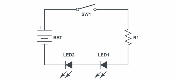
Be sure to calculate the appropriate value for R1 based on your power supply and LEDs.
LEDs in Parallel: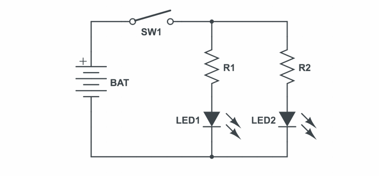
You can use a barrel jack to breadboard connector for power, it has 3 pins one of which is used to secure it on the breadboard. The following image should be helpful.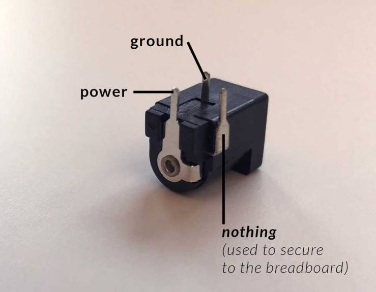
Part 2: DIY Switch
Craft a custom switch and replace the button in one of your circuits from Part 1 with your switch. You can search for examples of DIY switches online for inspiration.
Part 3: Creative Enclosure
Using one of the circuits you made in Part 1 and the DIY switch from Part 2, build a creative enclosure that conceals your breadboard and other hardware. Think about a creative way for the LEDs to peek out, or illuminate some part of your enclosure. You should completely hide the electronics inside your enclosure, only the switch and LEDs can be exposed. Think about a creative way that someone could interact with this simple circuit.
Blog Response
Thoroughly document each part of your lab and post it to your blog. Your post should include photos of each working circuit and explain in writing what each circuit does, and include a schematic drawing for each. Document your lab in a step-by-step format and please focus on posting informative and clear photos!
